
Part Datasheet Search > FET Drivers > IR2103 Datasheet PDF
Images are for reference
IR2103 Datasheet PDF
| Part Series: | IR2103 Series |
| Category: | FET Drivers |
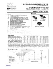
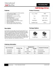
| Description: | Half Bridge Driver, Separate High and Low Side Inputs, Inverting Low Side Input, Fixed 520ns Deadtime in a 8Pin DIP package |
| Document: | IR2103STRPBF Datasheet PDF (37 Pages) |
IR2103 FET Drivers Datasheet PDF

IR2103 Datasheet PDF FET Drivers
18 Pages
International Rectifier
Driver 600V 0.36A 2Out Hi/Lo Side Half Brdg Inv/Non-Inv 8Pin PDIP Tube
18 Pages
International Rectifier
Half Bridge Driver, Separate High and Low Side Inputs, Inverting Low Side Input, Fixed 520ns Deadtime in a 8Pin DIP package
18 Pages
International Rectifier
Driver 600V 0.36A 2Out Hi/Lo Side Half Brdg Inv/Non-Inv 8Pin SOIC Tube
18 Pages
Infineon
Driver 600V 0.36A 2Out Hi/Lo Side Half Brdg Inv/Non-Inv 8Pin SOIC
18 Pages
Infineon
Driver 600V 0.36A 2Out Hi/Lo Side Half Brdg Inv/Non-Inv 8Pin SOIC T/R
Part Datasheet PDF Search
72,405,303 Parts Datasheet PDF, Update more than 5,000 PDF files ervery day.