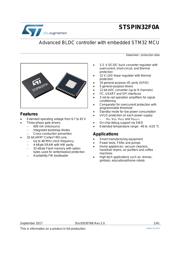
●The STSPIN32F0 is a System-In-Package providing an integrated solution suitable for driving three-phase BLDC motors using different driving modes.
●It embeds a triple half-bridge gate driver able to drive power MOSFETs or IGBTs with a current capability of 600 mA (sink and source). The high- and low-side switches of same half-bridge cannot be simultaneously driven high thanks to an integrated interlocking function.
●An internal DC/DC buck converter provides the 3.3 V voltage suitable to supply both the MCU and external components. An internal LDO linear regulator provides the supply voltage for gate drivers.
●The integrated operational amplifiers are available for the signal conditioning of the analog Hall-effect sensors and the shunt resistor signal.
●A comparator with a programmable threshold is integrated to perform the overcurrent protection.
●The integrated MCU (STM32F031C6 with extended temperature range, suffix 7 version) allows performing field-oriented control, the 6-step sensorless and other advanced driving algorithm including the speed control loop. It has the write-protection and read-protection feature for the embedded Flash memory to protect against unwanted writing and/or reading.
●The STSPIN32F0 device also features overtemperature and undervoltage lockout protections and can be put in the standby mode to reduce the power consumption. The device provides 16 general-purpose I/O ports (GPIO) with the 5 V tolerant capability, one 12-bit analog-to-digital converter with up to 9 channels performing conversions in a single-shot or scan modes, 5 synchronizable general-purpose timers and supports an easy to use debugging serial interface (SWD).
●Key Features
● Extended operating voltage from 8 to 45 V
● Three-phase gate drivers
● 600 mA sink/source
● Integrated bootstrap diodes
● Cross-conduction prevention
● 32-bit ARM® Cortex® -M0 core:
● Up to 48 MHz clock frequency
● 4-kByte SRAM with HW parity
● 32-kByte Flash memory with option bytes used for write/readout protection
● 3.3. V DC/DC buck converter regulator with overcurrent, short-circuit, and thermal protection
● 12 V LDO linear regulator with thermal protection
● 16 general-purpose I/O ports (GPIO)
● 5 general-purpose timers
● 12-bit ADC converter (up to 9 channels)
● I2 C, USART and SPI interfaces
● 4 rail-to-rail operation amplifiers for signal conditioning
● Comparator for overcurrent protection with programmable threshold
● 3FG open-drain output providing the decoded result of 3 Hall sensors inputs
● Standby mode for low power consumption
● UVLO protection on each power supply:
● VM , VDD , VREG and VBOOTx
● On-chip debug support via SWD
● Extended temperature range: -40 to +125 °C