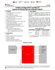
●The TCA9555PWR is a 16-bit I/O Expander for the two-line bidirectional bus (I²C) is designed for 1.65 to 5.5V VCC operation. It provides general-purpose remote I/O expansion for most microcontroller families via the I²C interface. The TCA9555 consists of two 8-bit configuration (input or output selection), input port, output port and polarity inversion (active high or active low operation) registers. At power on, the I/Os are configured as inputs. The system master can enable the I/Os as either inputs or outputs by writing to the I/O configuration bits. The data for each input or output is kept in the corresponding Input or Output register. The polarity of the Input Port register can be inverted with the Polarity Inversion register. Three hardware pins (A0, A1 and A2) are used to program the I²C address, which allows up to eight TCA9555 devices to share the same I²C bus or SMBus.
● Open-drain active-low interrupt (INT)\ output
● 400kHz Fast I²C bus
● Compatible with most microcontrollers
● Configurable slave address with 3 address pins
● Polarity inversion register
● Latched outputs with high-current drive capability for directly driving LEDs
● Latch-up performance exceeds 100mA per JESD 78, class II
● 3.5µA Maximum low standby-current consumption
● 5V Tolerant i/o ports
● Green product and no Sb/Br
●Device has limited built-in ESD protection. The leads should be shorted together or the device placed in conductive foam during storage or handling to prevent electrostatic damage to the MOS gates.