Part Datasheet Search > Voltage Regulators > TL494 Datasheet PDF
Images are for reference
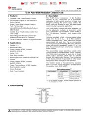
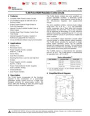
TL494 Datasheet PDF

Part Series:TL494 Series
Category:Voltage Regulators
Description:Voltage Mode PWM Controller 40V 200mA 300kHz 16Pin SOIC T/R
Document:TL494CN Datasheet PDF (35 Pages)

TL494 Datasheet PDF Voltage Regulators

34 Pages
TI
Voltage Mode PWM Controller 40V 200mA 300kHz 16Pin SOIC Tube
34 Pages
TI
Voltage Mode PWM Controller 40V 200mA 300kHz 16Pin SOIC Tube
34 Pages
TI
Voltage Mode PWM Controller 40V 200mA 300kHz 16Pin SOP T/R
34 Pages
TI
Voltage Mode PWM Controller 40V 200mA 300kHz 16Pin SOIC T/R
34 Pages
TI
Voltage Mode PWM Controller 40V 200mA 300kHz 16Pin SOIC T/R
34 Pages
TI
Voltage Mode PWM Controller 40V 200mA 300kHz 16Pin TSSOP T/R
34 Pages
TI
Voltage Mode PWM Controller 40V 200mA 300kHz 16Pin SOIC Tube
34 Pages
TI
Voltage Mode PWM Controller 40V 200mA 300kHz 16Pin SOP T/R
34 Pages
TI
Voltage Mode PWM Controller 40V 200mA 300kHz 16Pin SOP Tube
34 Pages
TI
Voltage Mode PWM Controller 40V 200mA 300kHz 16Pin TSSOP Tube
34 Pages
TI
Voltage Mode PWM Controller 40V 200mA 300kHz 16Pin TSSOP Tube
34 Pages
ON Semiconductor
Voltage Mode PWM Controller 500mA 200kHz Automotive 16Pin SOIC Tube
34 Pages
TI
Voltage Mode PWM Controller 40V 200mA 300kHz 16Pin PDIP Tube
21 Pages
ON Semiconductor
Voltage Mode PWM Controller 500mA 200kHz Automotive 16Pin SOIC T/R
15 Pages
ON Semiconductor
Voltage Mode PWM Controller 500mA 200kHz Automotive 16Pin PDIP Tube
14 Pages
ON Semiconductor
Voltage Mode PWM Controller 500mA 200kHz Automotive 16Pin SOIC T/R

TL494CDR Specifications

TYPE
DESCRIPTION
Mounting Style
Surface Mount
Frequency
300 kHz
Number of Pins
16 Pin
Supply Voltage (DC)
7.00V (min)
Case/Package
SOIC-16
show more

TL494CDR Function Overview

The TL494CDR is a Pulse Width Modulation (PWM) Controller on a single chip. Designed primarily for power-supply control, this device offers the flexibility to tailor the power-supply control circuitry to a specific application. The TL494 device contains two error amplifiers, an on-chip adjustable oscillator, a dead-time control (DTC) comparator, a pulse-steering control flip-flop, a 5V, 5% precision regulator and output-control circuits. The error amplifiers exhibit a common-mode voltage range from -0.3V to VCC - 2V. The dead-time control comparator has a fixed offset that provides approximately 5% dead time. The on-chip oscillator can be bypassed by terminating RT to the reference output and providing a sawtooth input to CT, or it can drive the common circuits in synchronous multiple-rail power supplies. The uncommitted output transistors provide either common-emitter or emitter-follower output capability.
Output control selects single-ended or push-pull operation
Internal circuitry prohibits double pulse at either output
Variable dead time provides control over total range
Internal regulator provides a stable 5V Reference supply with 5% Tolerance
Circuit architecture allows easy synchronization
Green product and no Sb/Br
show more
Part Datasheet PDF Search
72,405,303 Parts Datasheet PDF, Update more than 5,000 PDF files ervery day.