Part Datasheet Search > Clock Generators > TI > CDCEL925PWG4 Datasheet PDF > CDCEL925PWG4 Datasheet Pages 4/38
CDCEL925PWG4 Datasheet - TI
| Manufacturer: | TI |
| Category: | Clock Generators |
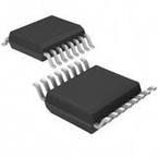
| Case Package: | TSSOP-16 |
| Description: | Clock Generator 8MHz to 160MHz Input 230MHz Output 16Pin TSSOP Tube |
| Pictures: |
CDCEL925PWG4Datasheet PDF
Page:
of 38 Go
If the format of the manual is confusing, please download and read the original PDF file.

1Xin/CLK 16 Xout
2S0 15 SDA/S1
3V
DD
14 SCL/S2
4V
Ctrl
13 Y1
5GND 12 GND
6 11 Y2
7Y4 10 Y3
8Y5 9
Not to scale
V
DDOUT
V
DDOUT
4
CDCE925
,
CDCEL925
SCAS847I –JULY 2007–REVISED OCTOBER 2016
www.ti.com
Product Folder Links: CDCE925 CDCEL925
Submit Documentation Feedback Copyright © 2007–2016, Texas Instruments Incorporated
(1) G = Ground, I = Input, O = Output, P = Power
5 Description (continued)
The deep M/N divider ratio allows the generation of zero-ppm audio/video, networking (WLAN, Bluetooth,
Ethernet, GPS), or interface (USB, IEEE1394, memory stick) clocks from a 27-MHz reference input frequency,
for example.
All PLLs support SSC (spread-spectrum clocking). SSC can be center-spread or down-spread clocking, which is
a common technique to reduce electromagnetic interference (EMI).
Based on the PLL frequency and the divider settings, the internal loop filter components are automatically
adjusted to achieve high stability and optimized jitter transfer characteristic of each PLL.
The device supports nonvolatile EEPROM programming for easy customization of the device in the application. It
is preset to a factory default configuration and can be reprogrammed to a different application configuration
before it goes onto the PCB or reprogrammed by in-system programming. All device settings are programmable
through the SDA/SCL bus, a 2-wire serial interface.
Three, free programmable control inputs, S0, S1, and S2, can be used to select different frequencies, or change
the SSC setting for lowering EMI, or other control features like outputs disable to low, outputs in high-impedance
state, power down, PLL bypass, and so forth.
The CDCx925 operates in a 1.8-V environment and in a temperature range of –40°C to 85°C.
6 Pin Configuration and Functions
PW Package
16-Pin TSSOP
Top View
Pin Functions
PIN
TYPE
(1)
DESCRIPTION
NAME NO.
GND 5, 12 G Ground
SCL/S2 14 I
SCL: Serial clock input (default configuration), LVCMOS; internal pullup
S2: User-programmable control input; LVCMOS inputs; internal pullup
SDA/S1 15 I/O
SDA: Bidirectional serial data input/output (default configuration), LVCMOS; internal pullup
S1: User-programmable control input; LVCMOS inputs; internal pullup
S0 2 I User-programmable control input S0; LVCMOS inputs; internal pullup
V
Ctrl
4 I VCXO control voltage (leave open or pull up when not used)
V
DD
3 P 1.8-V power supply for the device
V
DDOUT
6, 9 P
CDCEL925: 1.8-V supply for all outputs
CDCE925: 3.3-V or 2.5-V supply for all outputs

