Part Datasheet Search > Clock Generators > TI > CDCEL925PWG4 Datasheet PDF > CDCEL925PWG4 Datasheet Pages 5/38
CDCEL925PWG4 Datasheet - TI
| Manufacturer: | TI |
| Category: | Clock Generators |
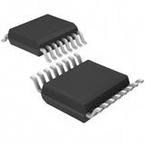
| Case Package: | TSSOP-16 |
| Description: | Clock Generator 8MHz to 160MHz Input 230MHz Output 16Pin TSSOP Tube |
| Pictures: |
CDCEL925PWG4Datasheet PDF
Page:
of 38 Go
If the format of the manual is confusing, please download and read the original PDF file.

5
CDCE925
,
CDCEL925
www.ti.com
SCAS847I –JULY 2007–REVISED OCTOBER 2016
Product Folder Links: CDCE925 CDCEL925
Submit Documentation FeedbackCopyright © 2007–2016, Texas Instruments Incorporated
Pin Functions (continued)
PIN
TYPE
(1)
DESCRIPTION
NAME NO.
Xin/CLK 1 I Crystal oscillator input or LVCMOS clock Input (selectable through SDA/SCL bus)
Xout 16 O Crystal oscillator output (leave open or pull up when not used)
Y1 13
O LVCMOS output
Y2 11
Y3 10
Y4 7
Y5 8
(1) Stresses beyond those listed under Absolute Maximum Ratings may cause permanent damage to the device. These are stress ratings
only, and functional operation of the device at these or any other conditions beyond those indicated under Recommended Operating
Conditions is not implied. Exposure to absolute-maximum-rated conditions for extended periods may affect device reliability.
(2) The input and output negative voltage ratings may be exceeded if the input and output clamp-current ratings are observed.
(3) SDA and SCL can go up to 3.6 V as stated in the Recommended Operating Conditions table.
7 Specifications
7.1 Absolute Maximum Ratings
over operating free-air temperature range (unless otherwise noted)
(1)
MIN MAX UNIT
Supply voltage, V
DD
–0.5 2.5 V
Input voltage, V
I
(2)(3)
–0.5 V
DD
+ 0.5 V
Output voltage, V
O
(2)
–0.5 V
DD
+ 0.5 V
Input current, I
I
(V
I
< 0, V
I
> V
DD
) 20 mA
Continuous output current, I
O
50 mA
Maximum junction temperature, T
J
125 °C
Storage temperature, T
stg
–65 150 °C
(1) JEDEC document JEP155 states that 500-V HBM allows safe manufacturing with a standard ESD control process.
(2) JEDEC document JEP157 states that 250-V CDM allows safe manufacturing with a standard ESD control process.
7.2 ESD Ratings
VALUE UNIT
V
(ESD)
Electrostatic discharge
Human-body model (HBM), per ANSI/ESDA/JEDEC JS-001
(1)
±2000
V
Charged-device model (CDM), per JEDEC specification JESD22-C101
(2)
±1500
7.3 Recommended Operating Conditions
MIN NOM MAX UNIT
V
DD
Device supply voltage 1.7 1.8 1.9 V
V
DDOUT
Output Yx supply voltage
CDCE925 2.3 3.6
V
CDCEL925 1.7 1.9
V
IL
Low-level input voltage LVCMOS 0.3 × V
DD
V
V
IH
High-level input voltage LVCMOS 0.7 × V
DD
V
V
I(thresh)
Input voltage threshold LVCMOS 0.5 × V
DD
V
V
I(S)
Input voltage
S0 0 1.9
V
S1, S2, SDA, SCL; V
(Ithresh)
= 0.5 V
DD
0 3.6
V
I(CLK)
Input voltage, CLK 0 1.9 V
I
OH
/I
OL
Output current
V
DDOUT
= 3.3 V ±12
mAV
DDOUT
= 2.5 V ±10
V
DDOUT
= 1.8 V ±8
C
L
Output load LVCMOS 15 pF

