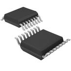
Part Datasheet Search > Microcontrollers > NXP > MC9S08QE8CTGR Datasheet PDF
MC9S08QE8CTGR Datasheet PDF - NXP
| Manufacturer: | NXP |
| Category: | Microcontrollers |
| Case Package: | TSSOP-16 |
| Description: | MCU 8Bit S08 CISC 8KB Flash 2.5V/3.3V 16Pin TSSOP T/R |
| Documentation: | MC9S08QE8CTGR Datasheet (4 Pages)MC9S08QE8CTGR User Reference Manual Guide (324 Pages)MC9S08QE8CTGR Programming Manual (2 Pages)MC9S08QE8CTGR Application Note (32 Pages) |
| Pictures: |
MC9S08QE8CTGR Datasheet PDF
ADatasheet has not yet included the datasheet for MC9S08QE8CTGR
If necessary, please send a supplementary document request to the administrator

MC9S08QE8CTGR Datasheet PDF (4 Pages)
MC9S08QE8CTGR Specifications
| TYPE | DESCRIPTION |
|---|---|
| Mounting Style | Surface Mount |
| Frequency | 20 MHz |
| Number of Pins | 16 Pin |
| Case/Package | TSSOP-16 |
| Halogen Free Status | Halogen Free |
| RAM Memory Size | 512 x 8 |
| Operating Temperature (Max) | 85 ℃ |
| Operating Temperature (Min) | -40 ℃ |
MC9S08QE8CTGR Size & Package
| TYPE | DESCRIPTION |
|---|---|
| Product Lifecycle Status | Unknown |
| Packaging | Tape & Reel (TR) |
| Size-Length | 5 mm |
| Size-Width | 4.4 mm |
| Size-Height | 1.05 mm |
| Operating Temperature | -40℃ ~ 85℃ (TA) |
MC9S08QE8CTGR Environmental
MC9S08QE8CTGR Function Overview
Overview
●The S08QE family, comprised of a pin-compatible 8-bit and 32-bit device duo, is Our first family in the Flexis series. The Flexis series of controllers is the connection point of the NXP® Controller Continuum where 8- and 32-bit compatibility become reality.
●The S08QE128 pushes the boundaries of the 8-bit architecture performance with 128 KB of flash, 24 analog-to-digital converter (ADC) channels and delivering up 25 MHz in bus frequency. The 32-bit MCF51QE128 is pin-, peripheral- and tool-compatible with the 8-bit S08QE128 device. They share a common set of peripherals and development tools, delivering the ultimate in migration flexibility.
●MoreLess
●## Features
●### Power-Saving Features
● Two ultra-low-power stop modes, one of which allows limited use of peripherals
● New low-power run and wait modes
● 6 µs typical wake up time from stop mode
● Internal clock Source (ICS)—module containing a frequency locked-loop (FLL) controlled by internal or external reference
● Oscillator (OSC)—loop-control Pierce oscillator
● crystal or ceramic resonator range of 31.25 kHz to 38.4 kHz or 1 MHz to 16 MHz
● Clock gating disables clocks to unused peripherals
●### 8-bit HCS08 Central Processing Unit (CPU)
● Up to 20 MHZ HCS08 CPU from 1.8V to 3.6V and across temperature range of -40°C to +85°C
● HCS08 instruction set with added BGND instruction
● Support for up to 32 interrupt/reset sources
●### On-Chip Memory
● Up to 128 KB flash read/program/erase over full operating voltage and temperature
● Up to 8 KB random-access memory (RAM)
●### Peripherals
● Two analog comparator (ACMP)
● Option to compare to an internal reference
● Output can be optionally routed to TPM as input capture trigger
● Analog Digital Converter (ADC)
● Up to 24-channel
● 12-bit resolution
● 2.5 µs conversion time
● Automatic compare function
● 1.7 mV/°C temperature sensor
● Internal bandgap reference channel
● Operation in low-power stop3
● 2x Serial communications interface (SCI)
● Two modules 0ffering asynchronous communications
● 13-bit break option
● Flexible baud rate generator
● Double buffered transmit and receive
● Optional H/W parity checking and generation
● Up to 2x Serial Peripheral Interfaces (SPI)
● Two modules with full-duplex or single-wire bidirectional
● double-buffered transmit and receive
● master or slave mode
● MSB-first or LSB-first shifting
● Timer/pulse-width modulator (TPM)
● One 6-channel (TMP3)
● Two 3-channel (TPM1 and TPM2)
● Selectable input capture
● Output compare
● Or buffered edge- or center-aligned PWM on each channel
● Two I2C
● Up to 100 kbps with maximum bus loading
● Multi-master operation
● Programmable slave address
● Interrupt-driven byte-by-byte data transfer
● Supports broadcast mode and 10-bit addressing
●### Input/Output
● Up to 70 GPIO (General Purpose Input/Output), one input-only and one output-only pin
● 16 Keyboard Interrupts (KBI) pins with selectable polarity
●### System Protection
● Watchdog computer operating properly (COP) reset with option to run from dedicated 1 kHz internal clock source or bus clock
● Low-voltage detection with reset or interrupt, selectable trip points
● Illegal op code detection with reset
● Flash block protection
●### Development Support
● Single-wire background debug interface
● Breakpoint capability
● ICE debug module —debug module supports both tag and force breakpoints
● Three comparators
● Nine trigger modes
● Eight deep FIFO for storing change-of-flow addresses and event-only data
● Supports both tag and force breakpointsComparison Table
●### MC9S08QE Family Members
●| ADC Channels
●S08QE32| | | | | | | | |
●S08QE8| | | | | | | | |
●S08QE64| | | | | | | | |
●MCF51QE| | | | | | | | |
●S08QE4| | | | | | | | |
●S08QE96| | | | | | | | |
●S08QE128| | | | | | | | |
●S08QE16| | | | | | | | |
show more
MC9S08QE8CTGR Documents
MC9S08QE8 Documents
Part Datasheet PDF Search
Example: STM32F103
72,405,303 Parts Datasheet PDF, Update more than 5,000 PDF files ervery day.
Relate Parts
Relate Documentations: MC9S08 DatasheetMC9S08 Pinout

