Part Datasheet Search > TI > SN65LVDT348 Datasheet PDF
SN65LVDT348 Datasheet PDF - TI
| Manufacturer: | TI |
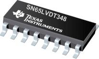
| Case Package: | TSSOP-16 |
| Description: | Quad LVDS Receiver with -4 to 5V Common-mode Range |
| Documentation: | SN65LVDT348 Datasheet (28 Pages)Package Outline Dimension on18 Page20 Page21 Page |
| Pictures: |
SN65LVDT348 Datasheet PDF
ADatasheet has not yet included the datasheet for SN65LVDT348
If necessary, please send a supplementary document request to the administrator

SN65LVDT348 Datasheet PDF (28 Pages)
SN65LVDT348 Specifications
| TYPE | DESCRIPTION |
|---|---|
| Case/Package | TSSOP-16 |
SN65LVDT348 Size & Package
| TYPE | DESCRIPTION |
|---|
SN65LVDT348 Environmental
SN65LVDT348 Function Overview
The SN65LVDS348, SN65LVDT348, SN65LVDS352, and SN65LVDT352 are high-speed, quadruple differential receivers with a wide common-mode input voltage range. This allows receipt of TIA/EIA-644 signals with up to 3-V of ground noise or a variety of differential and single-ended logic levels. The 348 is in a 16-pin package to match the industry-standard footprint of the DS90LV048. The 352 adds two additional VCC and GND pins in a 24-pin package to provide higher data transfer rates with multiple receivers in operation. All offer a flow-through architecture with all inputs on one side and outputs on the other to ease board layout and reduce crosstalk between receivers. LVDT versions of both integrate a 110- line termination resistor.
●These receivers also provide 3x the standards minimum common-mode noise voltage tolerance. The 4 V to 5 V common-mode range allows usage in harsh operating environments or accepts LVPECL, PECL, LVECL, ECL, CMOS, and LVCMOS levels without level shifting circuitry. See the Application Information Section for more details on the ECL/PECL to LVDS interface.
●Precise control of the differential input voltage thresholds allows for inclusion of 50 mV of input-voltage hysteresis to improve noise rejection. The differential input thresholds are still no more than ±50 mV over the full input common-mode voltage range.
●The receiver inputs can withstand ±15 kV human-body model (HBM), with respect to ground, without damage. This provides reliability in cabled and other connections where potentially damaging noise is always a threat.
●The receivers also include a (patent-pending) failsafe circuit that provides a high-level output within 600 ns after loss of the input signal. The most common causes of signal loss are disconnected cables, shorted lines, or powered-down transmitters. This prevents noise from being received as valid data under these fault conditions. This feature may also be used for Wired-Or bus signaling.
●The SN65LVDT348 and SN65LVDT352 include an integrated termination resistor. This reduces board space requirements and parts count by eliminating the need for a separate termination resistor. This can also improve signal integrity at the receiver by reducing the stub length from the line termination to the receiver.
●The intended application of these devices and signaling technique is for point-to-point baseband data transmission over controlled impedance media of approximately 100 . The transmission media may be printed-circuit board traces, backplanes, or cables. The ultimate rate and distance of data transfer is dependent upon the attenuation characteristics of the media and the noise coupling to the environment.
●The SN65LVDS348, SN65LVDT348, SN65LVDS352 and SN65LVDT352 are characterized for operation from 40°C to 85°C.
● Meets or Exceeds the Requirements of ANSI TIA/EIA-644A Standard
● Single-Channel Signaling Rates1 up to 560 Mbps
● 4 V to 5 V Common-Mode Input Voltage Range
● Flow-Through Architecture
● Active Failsafe Assures a High-level Output When an Input Signal Is not Present
● SN65LVDS348 Provides a Wide Common-Mode Range Replacement for the SN65LVDS048A or the DS90LV048A
● APPLICATIONS
● Logic Level Translator
● Point-to-Point Baseband Data Transmission Over 100- Media
● ECL/PECL-to-LVTTL Conversion
● Wireless Base Stations
● Central Office or PABX Switches
●1The signaling rate of a line is the number of voltage transitions that are made per second expressed in the units bps (bits per second).
show more
SN65LVDT348 Documents
SN65 Documents
TI
TEXAS INSTRUMENTS SN65HVD3082EDR RS485 Transceiver IC, 1 Driver, 200Kbps, 4.5V to 5.5V, SOIC-8
TI
TEXAS INSTRUMENTS SN65HVD1050DR CAN Bus, Transceiver, CAN, 1, 1, 4.5V, 5.5V, SOIC
TI
RS-485 Half-Duplex RS-485 Transceiver Single Transmitter/Receiver RS-485 8Pin SOIC T/R
TI
RS-485 Low-Power RS-485 Transceiver Single Transmitter/Receiver RS-485 8Pin SOIC Tube
Part Datasheet PDF Search
Example: STM32F103
72,405,303 Parts Datasheet PDF, Update more than 5,000 PDF files ervery day.
Relate Parts
Popular Parts
New Parts

