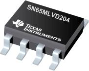
Part Datasheet Search > TI > SN65MLVD204 Datasheet PDF
SN65MLVD204 Datasheet PDF
ADatasheet has not yet included the datasheet for SN65MLVD204
If necessary, please send a supplementary document request to the administrator

SN65MLVD204 Datasheet PDF (31 Pages)
SN65MLVD204 Environmental
SN65MLVD204 Export Classifications
SN65MLVD204 Function Overview
This series of SN65MLVD20x devices are low-voltage differential line drivers and receivers complying with the proposed multipoint low-voltage differential signaling (M-LVDS) standard (TIA/EIA899). These circuits are similar to their TIA/EIA-644 standard compliant LVDS counterparts, with added features to address multipoint applications. Driver output current has been increased to support doubly-terminated, 50- load multipoint applications. Driver output slew rates are optimized for signaling rates up to 100 Mbps.
●Types 1 and 2 receivers are available. Both types of receivers operate over a common-mode voltage range of 1 V to 3.4 V to provide increased noise immunity in harsh electrical environments. Type-1 receivers have their differential input voltage thresholds near zero volts (±50 mV), and include 25 mV of hysteresis to prevent output oscillations in the presence of noise. Type-2 receivers include an offset threshold to detect open-circuit, idle-bus, and other fault conditions, and provide a known output state under these conditions.
●The intended application of these devices is in half-duplex or multipoint baseband data transmission over controlled impedance media of approximately 100- characteristic impedance. The transmission media may be printed circuit board traces, backplanes, or cables. (Note: The ultimate rate and distance of data transfer is dependent upon the attenuation characteristics of the media, the noise coupling to the environment, and other application-specific characteristics).
●These devices are characterized for operation from 40°C to 85°C.
● Low-Voltage Differential 30- up to 100 Mbps
● Power Dissipation at 100 Mbps
● Driver: 50 mW Typical
● Receiver: 30 mW Typical
● Meets or Exceeds Current Revision of M-LVDS Standard TIA/EIA899 for Multipoint Data Interchange
● Controlled Driver Output Voltage Transition Times for Improved Signal Quality
● 1-V to 3.4-V Common-Mode Voltage Range Allows Data Transfer With up to 2 V of Ground Noise
● Type-1 Receivers Incorporate 25 mV of Hysteresis
● Type-2 Receivers Provide an Offset (100 mV) Threshold to Detect Open-Circuit and Idle-Bus Conditions
● Operates From a Single 3.3-V Supply
● Propagation Delay Times Typically 2.3 ns for Drivers and 5 ns for Receivers
● Power-Up/Down Glitch-Free Driver
● Driver Handles Operation Into a Continuous Short Circuit Without Damage
● Bus Pins High Impedance When Disabled or VCC ≤ 1.5V
● 200-Mbps Devices Available (SN65MLVD201, 203, 206, and 207)
●The signaling rate of a line is the number of voltage transitions that are made per second expressed in bps (bits per second) units.
show more
SN65 Documents
TI
TEXAS INSTRUMENTS SN65HVD3082EDR RS485 Transceiver IC, 1 Driver, 200Kbps, 4.5V to 5.5V, SOIC-8
TI
TEXAS INSTRUMENTS SN65HVD1050DR CAN Bus, Transceiver, CAN, 1, 1, 4.5V, 5.5V, SOIC
TI
RS-485 Half-Duplex RS-485 Transceiver Single Transmitter/Receiver RS-485 8Pin SOIC T/R
TI
RS-485 Low-Power RS-485 Transceiver Single Transmitter/Receiver RS-485 8Pin SOIC Tube
Part Datasheet PDF Search
Example: STM32F103
72,405,303 Parts Datasheet PDF, Update more than 5,000 PDF files ervery day.

