Part Datasheet Search > AC-DC Converters > Linear Technology > LTC1966CMS8#PBF Datasheet PDF > LTC1966CMS8#PBF Application Note Pages 1/20
LTC1966CMS8#PBF Application Note - Linear Technology
| Manufacturer: | Linear Technology |
| Category: | AC-DC Converters |
| Case Package: | MSOP-8 |
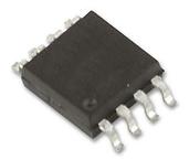
| Description: | LINEAR TECHNOLOGY LTC1966CMS8#PBF RMS to DC Converter, 0.1%, 6kHz, 0 °C, 70℃, MSOP, 8Pins |
| Pictures: |
LTC1966CMS8#PBFDatasheet PDF
Page:
of 20 Go
If the format of the manual is confusing, please download and read the original PDF file.

Application Note 106
AN106-1
an106f
February 2007
Figure 1. Primary Differences in RMS to DC Converter Family are Bandwidth and Supply Requirements.
All Devices Have Rail-to-Rail Differential Inputs and Output
Instrumentation Circuitry Using RMS-to-DC Converters
RMS Converters Rectify Average Results
Jim Williams
INTRODUCTION
It is widely acknowledged that RMS (Root of the Mean
of the Square) measurement of waveforms furnishes
the most accurate amplitude information.
1
Rectify-and-
average schemes, usually calibrated to a sine wave, are
only accurate for one waveshape. Departures from this
waveshape result in pronounced errors. Although accurate,
RMS conversion often entails limited bandwidth, restricted
range, complexity and diffi cult to characterize dynamic
and static errors. Recent developments address these
issues while simultaneously improving accuracy. Figure 1
shows the LTC
®
1966/LTC1967/LTC1968 device family. Low
frequency accuracy, including linearity and gain error, is
inside 0.5% with 1% error at bandwidths extending to
500kHz. These converters employ a sigma-delta based
computational scheme to achieve their performance.
2
Figure 2’s pinout descriptions and basic circuits reveal an
easily applied device. An output fi lter capacitor is all that is
required to form a functional RMS-to-DC converter. Split
and single supply powered variants are shown. Such ease
of implementation invites a broad range of application;
examples begin with Figure 3.
Isolated Power Line Monitor
BEFORE PROCEEDING ANY FURTHER, THE READER
IS WARNED THAT CAUTION MUST BE USED IN THE
CONSTRUCTION, TESTING AND USE OF THIS CIRCUIT.
HIGH VOLTAGE, LETHAL POTENTIALS ARE PRESENT IN
THIS CIRCUIT. EXTREME CAUTION MUST BE USED IN
WORKING WITH, AND MAKING CONNECTIONS TO, THIS
CIRCUIT. REPEAT: THIS CIRCUIT CONTAINS DANGER-
OUS, HIGH VOLTAGE POTENTIALS. USE CAUTION.
Figure 3’s AC power line monitor has 0.5% accuracy over
a sensed 90VAC to 130VAC input and provides a safe, fully
isolated output. RMS conversion provides accurate report-
ing of AC line voltage regardless of waveform distortion,
which is common.
1
See Appendix A, “RMS-to-DC Conversion” for complete discussion of
RMS measurement.
2
Appendix A details sigma-delta based RMS-to-DC converter operation.
, LT, LTC and LTM are registered trademarks of Linear Technology Corporation.
All other trademarks are the property of their respective owners.
PART NUMBER
LINEARITY
ERROR
TYP/MAX (%)
CONVERSION
GAIN ERROR
TYP/MAX (%)
1% ERROR
BANDWIDTH
(kHz)
3dB ERROR
BANDWIDTH
(kHz)
SUPPLY VOLTAGE I
SUPPLY
MAX (µA)
MIN(V) MAX(V)
LTC1966 0.02/0.15 0.1/0.3 6 800 2.7 ±5 170
LTC1967 0.02/0.15 0.1/0.3 200 4MHz 4.5 5.5 390
LTC1968 0.02/0.15 0.1/0.3 500 15MHz 4.5 5.5 2.3mA
Part Datasheet PDF Search
72,405,303 Parts Datasheet PDF, Update more than 5,000 PDF files ervery day.

