Part Datasheet Search > Logic ICs > ON Semiconductor > MC14543BDR2G Datasheet PDF > MC14543BDR2G Datasheet Pages 1/9
MC14543BDR2G Datasheet - ON Semiconductor
| Manufacturer: | ON Semiconductor |
| Category: | Logic ICs |
| Case Package: | SOIC-16 |
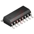
| Description: | ON SEMICONDUCTOR MC14543BDR2G BCD to 7 Segment Decoder / Driver / Latch, 7 Output, 3V to 18V, SOIC-16 |
| Pictures: |
MC14543BDR2GDatasheet PDF
Page:
of 9 Go
If the format of the manual is confusing, please download and read the original PDF file.

© Semiconductor Components Industries, LLC, 2014
July, 2014 − Rev. 10
1 Publication Order Number:
MC14543B/D
MC14543B
BCD-to-Seven Segment
Latch/Decoder/Driver for
Liquid Crystals
The MC14543B BCD−to−seven segment latch/decoder/driver is
designed for use with liquid crystal readouts, and is constructed with
complementary MOS (CMOS) enhancement mode devices.
The circuit provides the functions of a 4−bit storage latch and an 8421
BCD−to−seven segment decoder and driver. The device has the
capability to invert the logic levels of the output combination.
The phase (Ph), blanking (BI), and latch disable (LD) inputs are used
to reverse the truth table phase, blank the display, and store a BCD
code, respectively. For liquid crystal (LC) readouts, a square wave is
applied to the Ph input of the circuit and the electrically common
backplane of the display. The outputs of the circuit are connected
directly to the segments of the LC readout. For other types of readouts,
such as light−emitting diode (LED), incandescent, gas discharge, and
fluorescent readouts, connection diagrams are given on this data sheet.
Applications include instrument (e.g., counter, DVM etc.) display
driver, computer/calculator display driver, cockpit display driver, and
various clock, watch, and timer uses.
Features
• Latch Storage of Code
• Blanking Input
• Readout Blanking on All Illegal Input Combinations
• Direct LED (Common Anode or Cathode) Driving Capability
• Supply Voltage Range = 3.0 V to 18 V
• Capable of Driving 2 Low−power TTL Loads, 1 Low−power Schottky
TTL Load or 2 HTL Loads Over the Rated Temperature Range
• Pin−for−Pin Replacement for CD4056A (with Pin 7 Tied to V
SS
).
• Chip Complexity: 207 FETs or 52 Equivalent Gates
• NLV Prefix for Automotive and Other Applications Requiring
Unique Site and Control Change Requirements; AEC−Q100
Qualified and PPAP Capable.
• This Device is Pb−Free and is RoHS Compliant
http://onsemi.com
See detailed ordering and shipping information in the package
dimensions section on page 7 of this data sheet.
ORDERING INFORMATION
A = Assembly Location
WL, L = Wafer Lot
YY, Y = Year
WW, W = Work Week
G = Pb−Free Package
MARKING DIAGRAM
SOIC−16
D SUFFIX
CASE 751B
1
16
14543BG
AWLYWW
1
PIN ASSIGNMENT
13
14
15
16
9
10
11
125
4
3
2
1
8
7
6
d
e
g
f
V
DD
a
b
c
D
B
C
LD
V
SS
BI
PH
A
Downloaded from Arrow.com.
Part Datasheet PDF Search
72,405,303 Parts Datasheet PDF, Update more than 5,000 PDF files ervery day.

