
Part Datasheet Search > Switching Power Supplies > ST Microelectronics > VNB10N0713TR Datasheet PDF > VNB10N0713TR Datasheet Pages 1/14
VNB10N0713TRDatasheet PDF
Page:
of 14 Go
If the format of the manual is confusing, please download and read the original PDF file.

VNB10N07/K10N07FM
VNP10N07FI/VNV10N07
"OMNIFET":
FULLY AUTOPROTECTED POWER MOSFET
®
June 1998
BLOCK DIAGRAM (∗)
TYPE V
clamp
R
DS(on)
I
lim
VNB10N07
VNK10N07FM
VNP10N07FI
VNV10N07
70 V
70 V
70 V
70 V
0.1 Ω
0.1 Ω
0.1 Ω
0.1 Ω
10 A
10 A
10 A
10 A
■ LINEAR CURRENT LIMITATION
■ THERMAL SHUT DOWN
■ SHORT CIRCUIT PROTECTION
■ INTEGRATED CLAMP
■ LOW CURRENT DRAWN FROM INPUT PIN
■ DIAGNOSTIC FEEDBACK THROUGH INPUT
PIN
■ ESD PROTECTION
■ DIRECT ACCESS TO THE GATE OF THE
POWER MOSFET (ANALOG DRIVING)
■ COMPATIBLE WITH STANDARD POWER
MOSFET
DESCRIPTION
The VNB10N07, VNK10N07FM, VNP10N07FI
and VNV10N07 are monolithic devices made
using STMicroelectronics VIPower M0
Technology, intended for replacement of
standard power MOSFETS in DC to 50 KHz
applications. Built-in thermal shut-down, linear
current limitation and overvoltage clamp protect
the chip in harsh enviroments.
Fault feedback can be detected by monitoring the
voltage at the input pin.
1
10
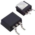
PowerSO-10
1
3
1
2
3
ISOWATT220
D2PAK
TO-263
SOT82-FM
(∗) PowerSO-10 Pin Configuration : INPUT = 6,7,8,9,10; SOURCE = 1,2,4,5; DRAIN = TAB
1/14
Part Datasheet PDF Search
72,405,303 Parts Datasheet PDF, Update more than 5,000 PDF files ervery day.