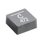
Part Datasheet Search > Single Inductors > Coilcraft > XFL4020-152MEC Datasheet PDF > XFL4020-152MEC Datasheet Pages 1/3
XFL4020-152MECDatasheet PDF
Page:
of 3 Go
If the format of the manual is confusing, please download and read the original PDF file.

HIGH TEMPERA
TURE
Shielded Power Inductors
–
XFL4020
Document 745-1
Document 745-1 Revised 07/18/12
Inductance
2
DCR (mOhms)
3
SRF typ
4
Isat (A)
5
Irms (A)
6
Part number
1
±20% (µH) typ max (MHz) 10% drop 20% drop 30% drop 20°C rise 40°C rise
XFL4020-102ME_ 1.0 10.80 11.90 64 4.5 5.1 5.4 8.0 11.0
XFL4020-152ME_ 1.5 14.40 15.80 59 4.1 4.4 4.6 6.7 9.1
XFL4020-222ME_ 2.2 21.35 23.50 38 3.1 3.5 3.7 6.0 8.0
XFL4020-332ME_ 3.3 34.80 38.30 33 2.7 2.8 2.9 3.9 5.2
XFL4020-472ME_ 4.7 52.20 57.40 26 2.0 2.5 2.7 3.6 5.0
1. When ordering, please specify termination and packaging codes:
XFL4020-472MEC
Termination: E = RoHS compliant tin-silver over copper.
Special order: T = RoHS tin-silver-copper (95.5/4/0.5) or S = non-RoHS tin-lead (63/37).
Packaging: C = 7″ machine-ready reel. EIA-481 embossed plastic tape (1000 parts per full reel).
B = Less than full reel. In tape, but not machine ready. To have a leader and trailer added
($25 charge), use code letter C instead.
D = 13″ machine-ready reel. EIA-481 embossed plastic tape. Factory order only, not stocked
(3500 parts per full reel).
2. Inductance tested at 100 kHz, 0.1 Vrms, 0 Adc.
3. DCR measured on a micro-ohmmeter.
4. SRF measured using Agilent/HP 4395A or equivalent.
5. DC current at 25°C that causes an inductance drop of 30% (typ) from its value without current.
Click for temperature derating information.
6. Current that causes the specified temperature rise from 25°C ambient. This information is for reference only
and does not represent absolute maximum ratings. Click for temperature derating information.
7. Electrical specifications at 25°C.
Refer to Doc 362 “Soldering Surface Mount Components” before soldering.
Designer’s Kit C436 contains 5 each of all values
Environmental RoHS compliant, halogen free
Terminations RoHS compliant tin-silver over copper. Other
terminations available at additional cost.
Core material Composite
Core and winding loss See www.coilcraft.com/coreloss
Weight 162 – 169 mg
Ambient temperature –40°C to +125°C with (40°C rise) Irms current.
Maximum part temperature +165°C (ambient + temp rise). Derating.
Storage temperature Component: –40°C to +165°C.
Tape and reel packaging: –40°C to +80°C
Resistance to soldering heat Max three 40 second reflows at
+260°C, parts cooled to room temperature between cycles
Moisture Sensitivity Level (MSL) 1 (unlimited floor life at <30°C /
85% relative humidity)
Failures in Time (FIT) / Mean Time Between Failures (MTBF)
38 per billion hours / 26,315,789 hours, calculated per Telcordia SR-332
Packaging 1000/7″ reel; 3500/13″ reel Plastic tape: 12 mm wide,
0.23 mm thick, 8 mm pocket spacing, 2.3 mm pocket depth
PCB washing Tested to MIL-STD-202 Method 215 plus an additional
aqueous wash. See Doc787_PCB_Washing.pdf.
• Exceptionally low DCR – 10.8 mOhm
• Excellent current handling capability
Irms Testing
Irms testing was performed on
0.75 inch wide × 0.25 inch thick
copper traces in still air.
Temperature rise is highly
dependent on many factors
including pcb land pattern, trace
size, and proximity to other com-
ponents. Therefore temperature
rise should be verified in appli-
cation conditions.

