Part Datasheet Search > TI > CC1350 Datasheet PDF
CC1350 Datasheet PDF
ADatasheet has not yet included the datasheet for CC1350
If necessary, please send a supplementary document request to the administrator

CC1350 Datasheet PDF (61 Pages)
CC1350 Environmental
CC1350 Function Overview
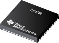
The CC1350 is a member of the CC26xx and CC13xx family of cost-effective, ultra-low-power, 2.4-GHz and Sub-1 GHz RF devices from Texas Instruments™. Very low active RF and microcontroller (MCU) current consumption, in addition to flexible low-power modes, provide excellent battery lifetime and allow long-range operation on small coin-cell batteries and in energy-harvesting applications.
●The CC1350 is the first device in the CC13xx and CC26xx family of cost-effective, ultra-low-power wireless MCUs capable of handling both Sub-1 GHz and 2.4-GHz RF frequencies. The CC1350 device combines a flexible, very low-power RF transceiver with a powerful 48-MHz ARM® Cortex®-M3 microcontroller in a platform supporting multiple physical layers and RF standards. A dedicated Radio Controller (Cortex®-M0) handles low-level RF protocol commands that are stored in ROM or RAM, thus ensuring ultra-low power and flexibility to handle both Sub-1 GHz protocols and 2.4 GHz protocols (for example _Bluetooth_® low energy). This enables the combination of a Sub-1 GHz communication solution that offers the best possible RF range together with a Bluetooth low energy smartphone connection that enables great user experience through a phone application. The Sub-1 GHz only device in this family is the CC1310.
●The CC1350 device is a highly integrated, true single-chip solution incorporating a complete RF system and an on-chip DC-DC converter.
●Sensors can be handled in a very low-power manner by a dedicated autonomous ultra-low-power MCU that can be configured to handle analog and digital sensors; thus the main MCU (Cortex-M3) can maximize sleep time.
●The CC1350 power and clock management and radio systems require specific configuration and handling by software to operate correctly, which has been implemented in the TI-RTOS. TI recommends using this software framework for all application development on the device. The complete TI-RTOS and device drivers are offered in source code free of charge.
● Worlds First Dual-Band (Sub-1 GHz and 2.4 GHz) Wireless Microcontroller
● Microcontroller
● Powerful ARM® Cortex®-M3 Processor
● EEMBC CoreMark® Score: 142
● EEMBC ULPBench™ Score: 158
● Clock Speed up to 48-MHz
● 128KB of In-System Programmable Flash
● 8KB of SRAM for Cache
●(or as General-Purpose RAM)
● 20KB of Ultra-Low-Leakage SRAM
● 2-Pin cJTAG and JTAG Debugging
● Supports Over-the-Air (OTA) Update
● Ultra-Low-Power Sensor Controller
● Can Run Autonomously From the Rest of the System
● 16-Bit Architecture
● 2KB of Ultra-Low-Leakage SRAM for Code and Data
● Efficient Code-Size Architecture, Placing Parts of
●TI-RTOS, Drivers,_ Bluetooth_® low energy Controller and Bootloader in ROM
● RoHS-Compliant Package
● 7-mm × 7-mm RGZ VQFN48 (30 GPIOs)
● 5-mm × 5-mm RHB VQFN32 (15 GPIOs)
● 4-mm × 4-mm RSM VQFN32 (10 GPIOs)
● Peripherals
● All Digital Peripheral Pins Can Be Routed to Any GPIO
● Four General-Purpose Timer Modules
●(Eight 16-Bit or Four 32-Bit Timers, PWM Each)
● 12-Bit ADC, 200 ksamples/s, 8-Channel Analog MUX
● Continuous Time Comparator
● Ultra-Low-Power Clocked Comparator
● Programmable Current Source
● UART
● 2× SSI (SPI, MICROWIRE, TI)
● I2C, I2S
● Real-Time Clock (RTC)
● AES-128 Security Module
● True Random Number Generator (TRNG)
● Support for Eight Capacitive Sensing Buttons
● Integrated Temperature Sensor
● External System
● On-Chip Internal DC-DC Converter
● Seamless Integration With the SimpleLink™ CC1190 and CC2592 Range Extenders
● Low Power
● Wide Supply Voltage Range: 1.8 to 3.8 V
● RX: 5.4 mA (Sub-1 GHz), 6.4 mA (Bluetooth low energy, 2.4 GHz)
● TX at +10 dBm: 13.4 mA (Sub-1 GHz)
● TX at +9 dBm: 22.3 mA (Bluetooth low energy, 2.4 GHz)
● TX at +0 dBm: 10.5 mA (Bluetooth low energy, 2.4 GHz)
● Active-Mode MCU 48 MHz Running Coremark: 2.5 mA (51 µA/MHz)
● Active-Mode MCU: 48.5 CoreMark/mA
● Active-Mode Sensor Controller at 24 MHz:
●0.4 mA + 8.2 µA/MHz
● Sensor Controller, One Wakeup Every Second Performing One 12-Bit ADC Sampling: 0.95 µA
● Standby: 0.7 µA (RTC Running and RAM and CPU Retention)
● Shutdown: 185 nA (Wakeup on External Events)
● RF Section
● 2.4-GHz RF Transceiver Compatible With Bluetooth low energy 4.2 Specification
● Excellent Receiver Sensitivity –124 dBm Using Long-Range Mode, –110 dBm at 50 kbps
●(Sub-1 GHz),
●–87 dBm at Bluetooth low energy
● Excellent Selectivity (±100 kHz): 56 dB
● Excellent Blocking Performance (±10 MHz):
●90 dB
● Programmable Output Power up to +15 dBm (Sub-1 GHz) and +9 dBm at 2.4 GHz (Bluetooth low energy)
● Single-Ended or Differential RF Interface
● Suitable for Systems Targeting Compliance With Worldwide Radio Frequency Regulations
● ETSI EN 300 220, EN 303 204 (Europe)
● EN 300 440 Class 2 (Europe)
● EN 300 328 (Europe)
● FCC CFR47 Part 15 (US)
● ARIB STD-T66 (Japan)
● ARIB STD-T108 (Japan)
● Wireless M-Bus and Selected IEEE® 802.15.4g PHY
● Tools and Development Environment
● Full-Feature and Low-Cost Development Kits
● Multiple Reference Designs for Different RF Configurations
● Packet Sniffer PC Software
● Sensor Controller Studio
● SmartRF™ Studio
● SmartRF Flash Programmer 2
● IAR Embedded Workbench® for ARM
● Code Composer Studio™
●All trademarks are the property of their respective owners.
show more
CC1350 Documents
Part Datasheet PDF Search
Example: STM32F103
72,405,303 Parts Datasheet PDF, Update more than 5,000 PDF files ervery day.

