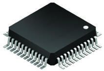
Part Datasheet Search > Microcontrollers > ST Microelectronics > STM32F051C8T6 Datasheet PDF > STM32F051C8T6 Datasheet Pages 113/121
STM32F051C8T6 Datasheet - ST Microelectronics
| Manufacturer: | ST Microelectronics |
| Category: | Microcontrollers |
| Case Package: | LQFP-48 |
| Description: | MCU 32Bit ARM Cortex M0 RISC 64KB Flash 2.5V/3.3V 48Pin LQFP Tray |
| Pictures: |
STM32F051C8T6Datasheet PDF
Page:
of 121 Go
If the format of the manual is confusing, please download and read the original PDF file.

DocID022265 Rev 6 113/121
STM32F051x4 STM32F051x6 STM32F051x8 Package information
115
Each temperature range suffix corresponds to a specific guaranteed ambient temperature at
maximum dissipation and, to a specific maximum junction temperature.
As applications do not commonly use the STM32F051xx at maximum dissipation, it is useful
to calculate the exact power consumption and junction temperature to determine which
temperature range will be best suited to the application.
The following examples show how to calculate
the temperature range needed for a given
application.
Example 1: High-performance application
Assuming the following application conditions:
Maximum ambient temperature T
Amax
= 82 °C (measured according to JESD51-2),
I
DDmax
= 50 mA, V
DD
= 3.5 V, maximum 20 I/Os used at the same time in output at low
level with I
OL
= 8 mA, V
OL
= 0.4 V and maximum 8 I/Os used at the same time in output
at low level with I
OL
= 20 mA, V
OL
= 1.3 V
P
INTmax
=
50 mA × 3.5 V= 175 mW
P
IOmax
=
20 × 8 mA × 0.4 V + 8 × 20 mA × 1.3 V = 272 mW
This gives: P
INTmax
= 175 mW and P
IOmax
= 272 mW:
P
Dmax
=
175
+
272 = 447 mW
Using the values obtained in Table 74 T
Jmax
is calculated as follows:
– For LQFP64, 45 °C/W
T
Jmax
= 82 °C + (45 °C/W × 447 mW) = 82 °C + 20.115 °C = 102.115 °C
This is within the range of the suffix 6 version parts (–40 < T
J
< 105 °C) see Table 20:
General operating conditions.
In this case, parts must be ordered at least with the temp
erature range suffix 6 (see
Section 8: Part numbering).
Note: With this given P
Dmax
we can find the T
Amax
allowed for a given device temperature range
(order code suffix 6 or 7).
Suffix 6: T
Amax
= T
Jmax
- (45°C/W × 447 mW) = 105-20.115 = 84.885 °C
Suffix 7: T
Amax
= T
Jmax
- (45°C/W × 447 mW) = 125-20.115 = 104.885 °C
Example 2: High-temperature application
Using the same rules, it is possible to address applications that run at high ambient
temperatures with a low dissipation, as long as junction temperature T
J
remains within the
specified range.
Assuming the following applic
ation conditions:
Maximum ambient temperature T
Amax
= 100 °C (measured according to JESD51-2),
I
DDmax
= 20 mA, V
DD
= 3.5 V, maximum 20 I/Os used at the same time in output at low
level with I
OL
= 8 mA, V
OL
= 0.4 V
P
INTmax
=
20 mA × 3.5 V= 70 mW
P
IOmax
=
20 × 8 mA × 0.4 V = 64 mW
This gives: P
INTmax
= 70 mW and P
IOmax
= 64 mW:
P
Dmax
=
70
+
64 = 134 mW
Thus: P
Dmax
= 134 mW
Part Datasheet PDF Search
72,405,303 Parts Datasheet PDF, Update more than 5,000 PDF files ervery day.

