Part Datasheet Search > ON Semiconductor > FL5160MX Datasheet PDF
FL5160MX Datasheet PDF - ON Semiconductor
| Manufacturer: | ON Semiconductor |
| Case Package: | SOIC-10 |
| Description: | Optocoupler Drive 20V 10Pin SOIC N T/R |
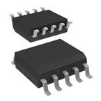
| Pictures: |
FL5160MX Datasheet PDF
ADatasheet has not yet included the datasheet for FL5160MX
If necessary, please send a supplementary document request to the administrator

FL5160MX Datasheet PDF (2 Pages)
FL5160MX Specifications
| TYPE | DESCRIPTION |
|---|---|
| Mounting Style | Surface Mount |
| Number of Pins | 10 Pin |
| Case/Package | SOIC-10 |
| Supply Current | 600 µA |
| Number of Positions | 10 Position |
| Operating Temperature (Max) | 85 ℃ |
| Operating Temperature (Min) | -40 ℃ |
| Supply Voltage | 16V ~ 18V |
| Supply Voltage (Max) | 5.5 V |
| Supply Voltage (Min) | 4.5 V |
FL5160MX Size & Package
| TYPE | DESCRIPTION |
|---|---|
| Product Lifecycle Status | Active |
| Packaging | Tape & Reel (TR) |
| Operating Temperature | -40℃ ~ 85℃ |
FL5160MX Environmental
FL5160MX Export Classifications
FL5160MX Function Overview
The FL5150 and FL5160 are controllers for varying the pulse width for AC loads. The FL5150 is for 50 Hz and the FL5160 is for 60 Hz applications. The FL5150/60 is powered from the AC line and generates a programmable gate drive for controlling the pulse width for external IGBT or MOSFET transistors. The pulse width can be user programmable with either an external resistor or 0 to 10 V DC signal or controlled by a µP with a logic signal. The pulse width can be controlled from 0 to 100% duty cycle to provide a wide AC symmetric dimming control function when biased with a 3-wire application. For 2-wire Line-Hot and Load-Hot applications, the pulse width can typically be varied from 0 to a maximum gate pulse so that the load voltage is >95% of the AC line voltage. The FL5150/60 will automatically override the pulse width control setting to allow maximum gate pulse width without flicker.The FL5150/60 takes advantage of the UL1472 2015 2nd edition code revision that allows for up to 0.5 mA of ground leakage current when a neutal wire is not available in the switch box. This improves the ficker performance for non-resistive loads. If the application does not allow ground leakage current then the Line Hot signal can be used as the ZC signal. The FL5150/60 has user programmable over-current and temperature protection. With external sense resistors, the maximum voltage drop across Q1 and Q2 can be set to limit the maximum current and transistor power dissipation. The FL5150/60 can be programmed for trailing edge dimming when the DIM Mode pin is low at startup (pulse width starts at the zero-crossing) or leadig edge dimming when the DIM Mode pin is connected to the VDD pin at startup (pulse width ends at the zero crossing). When an OFF state is selected (DIM Control pin is 0 V) the FL5150/60 will go into a low power electronic OFF state that reduces the power consumption to less than 100mW if an external NPN transistor is used.The FL5150/60 has an internal 8 bit ADC that allows for typically 226 selectable dimming pulse widths with a resolution of 25 µs per step. The FL5150/60 controls the dim pulse width rate of change so that the minimum to maximum dim ramp time is approximately 1 second. This feature allows for a smooth dim transition.Internally, the FL5150/60 contains a 17 V shunt regulator, 5 V linear regulator, 8Bit ADC, detection comparators, control logic and an IGBT or MOSFET gate driver. The 10-pin SOIC package provides for a low-cost, compact design and layout.
●Features
●---
● |
● Selectable Earth Ground or Line-Hot Zero Cross Detection: Complies with UL1472 2015 2nd Edition for Addition of Ground Leakage Current for Flicker Reduction (North America)
● User Programmable Leading or Trailing Edge Dimming Control
● Dynamic Over-Current and Temperature Protection
● Powered from the AC Line
● Symmetric AC Current Control
● IGBT or MOSFET Gate Driver
● Gate Pulse Width Programmable from 0 to 100% tON
● 8 Bit ADC Input for Dimming Control with an Adjustable Resistor or 0 to 10 V DC Voltage
● 226 Dimming Pulse Widths with 25 µs Resolution and Built-in Ramp Up/Down Control for Smooth Dimming
● Automatically Maximum Gate Pulse Width Control (Auto Max.)
● Minimum External Components
● 600 µA Quiescent Current
● Precision Temperature Compensated 2% Internal Timer
● Low Power Electronic Off State Mode
● 50 Hz and 60 Hz Options
● Space Savings SOIC 10-pin Package
show more
FL5160MX Documents
FL5160 Documents
Part Datasheet PDF Search
Example: STM32F103
72,405,303 Parts Datasheet PDF, Update more than 5,000 PDF files ervery day.

